Engine oil leak test system and method

a technology for engine oil leaks and test systems, applied in engine testing, structural/machine measurement, instruments, etc., can solve the problems of many small oil leaks that cannot be detected by manual leak testing methods, and the flow past the piston rings is dependent on variables that are difficult, if not impossible, to control

Inactive Publication Date: 2008-03-25
HONDA MOTOR CO LTD
View PDF24 Cites 7 Cited by
  • Summary
  • Abstract
  • Description
  • Claims
  • Application Information

AI Technical Summary

Benefits of technology

[0008]The present invention is directed toward a system and method for testing an engine for possible oil leaks, wherein the system is automated and wherein the method can be performed on an engine production line without interrupting the production timing or sequence.
[0010]In further accordance with the present invention, some of the head seal units are adapted to introduce pressurized air into the engine oil system, while at least one other head seal unit is adapted to provide pressurized air to an intake side of an EGR valve and thereby offset or compensate for air leakage inherent in the EGR valve.

Problems solved by technology

The amount of air that flows past the piston rings is dependent on variables that are difficult, if not impossible, to control.
Since many of the oil leaks are smaller than the blow-by, many small oil leaks cannot be detected by the manual leak testing method.

Method used

View more

Image

Smart Image Click on the blue labels to locate them in the text.
Viewing Examples
Smart Image
  • Engine oil leak test system and method
  • Engine oil leak test system and method
  • Engine oil leak test system and method

Examples

Experimental program
Comparison scheme
Effect test

Embodiment Construction

[0022]With reference to FIGS. 6-8, a portion of a production line incorporating an engine oil leak testing station 100 is schematically illustrated. The production line includes a conveyor belt 102 that extends through the testing station 100. The conveyor 102 transports partially assembled engines 10, each disposed upon a pallet 11, toward the testing station 100. The conveyor 102 also transports tested engines away from the testing station for further assembly or repair, depending upon the results of the oil leak test, as described hereinafter.

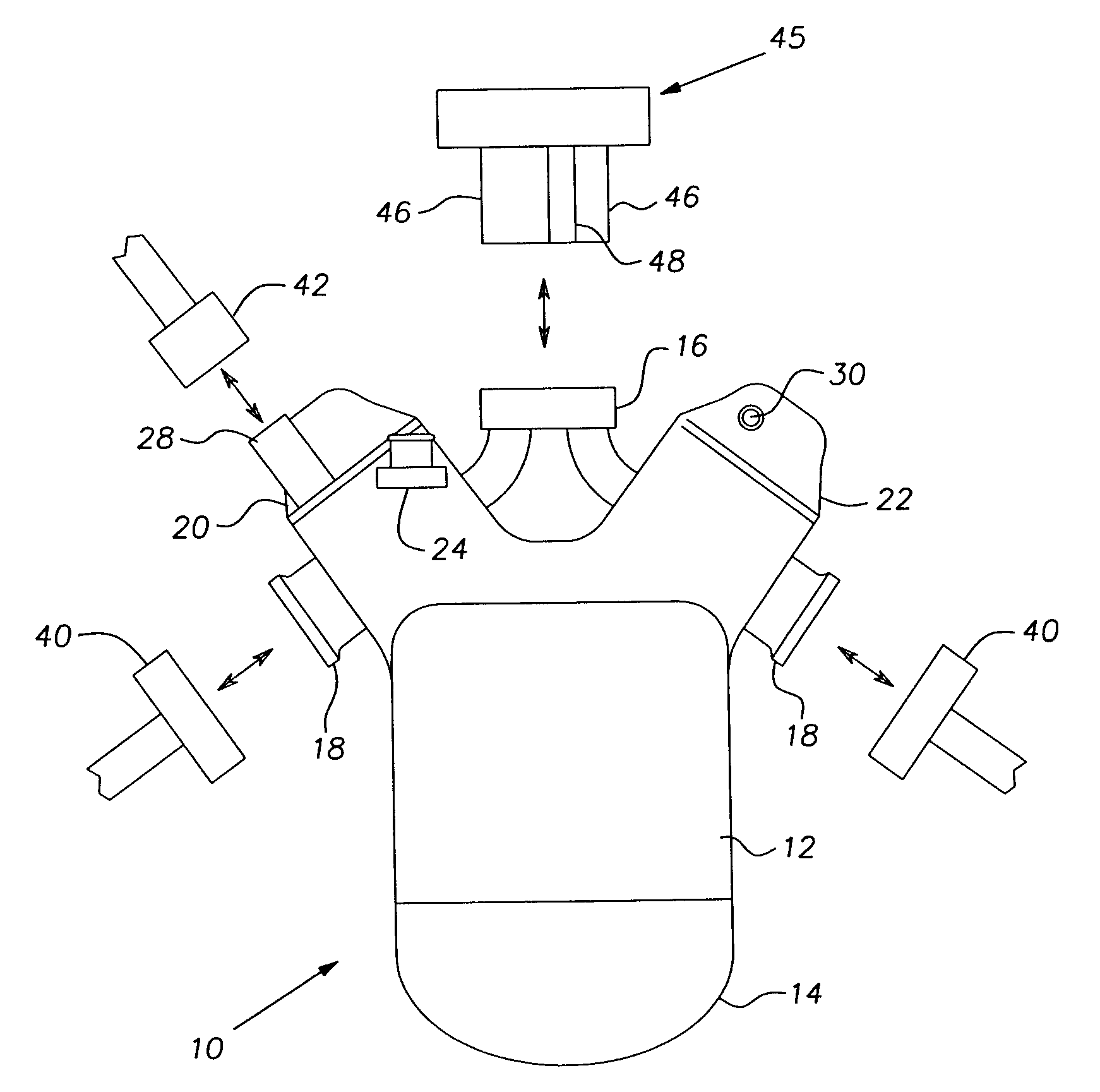
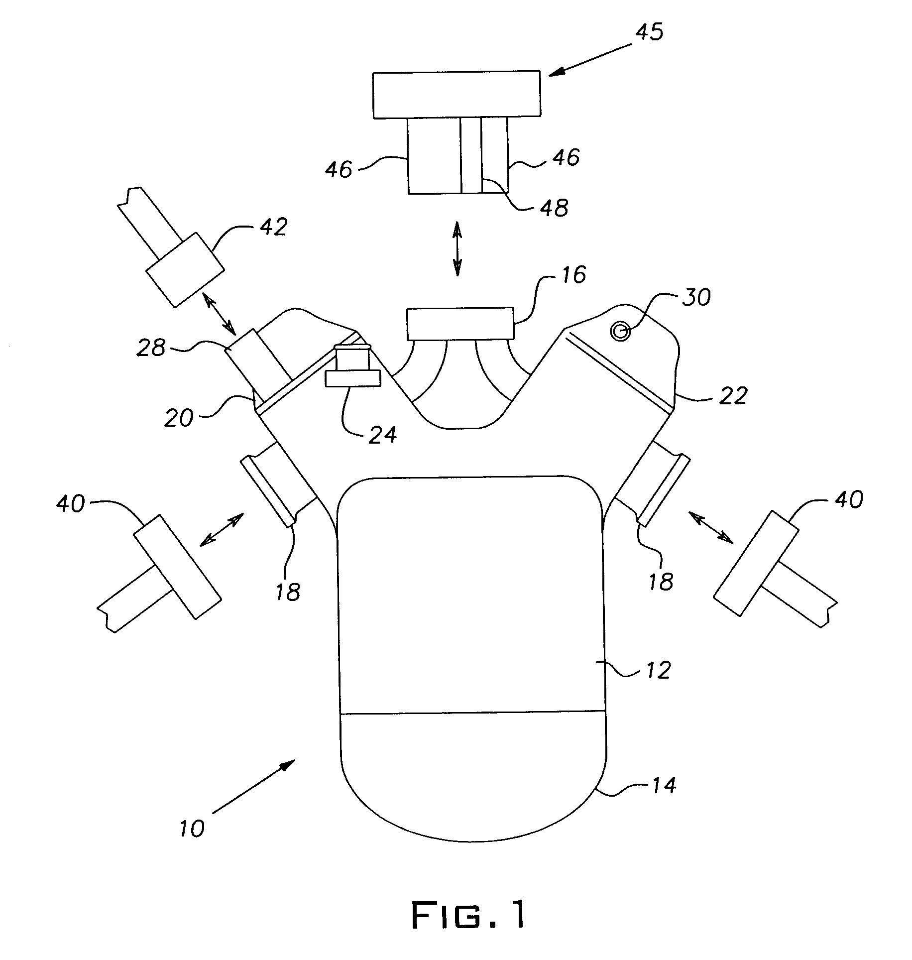
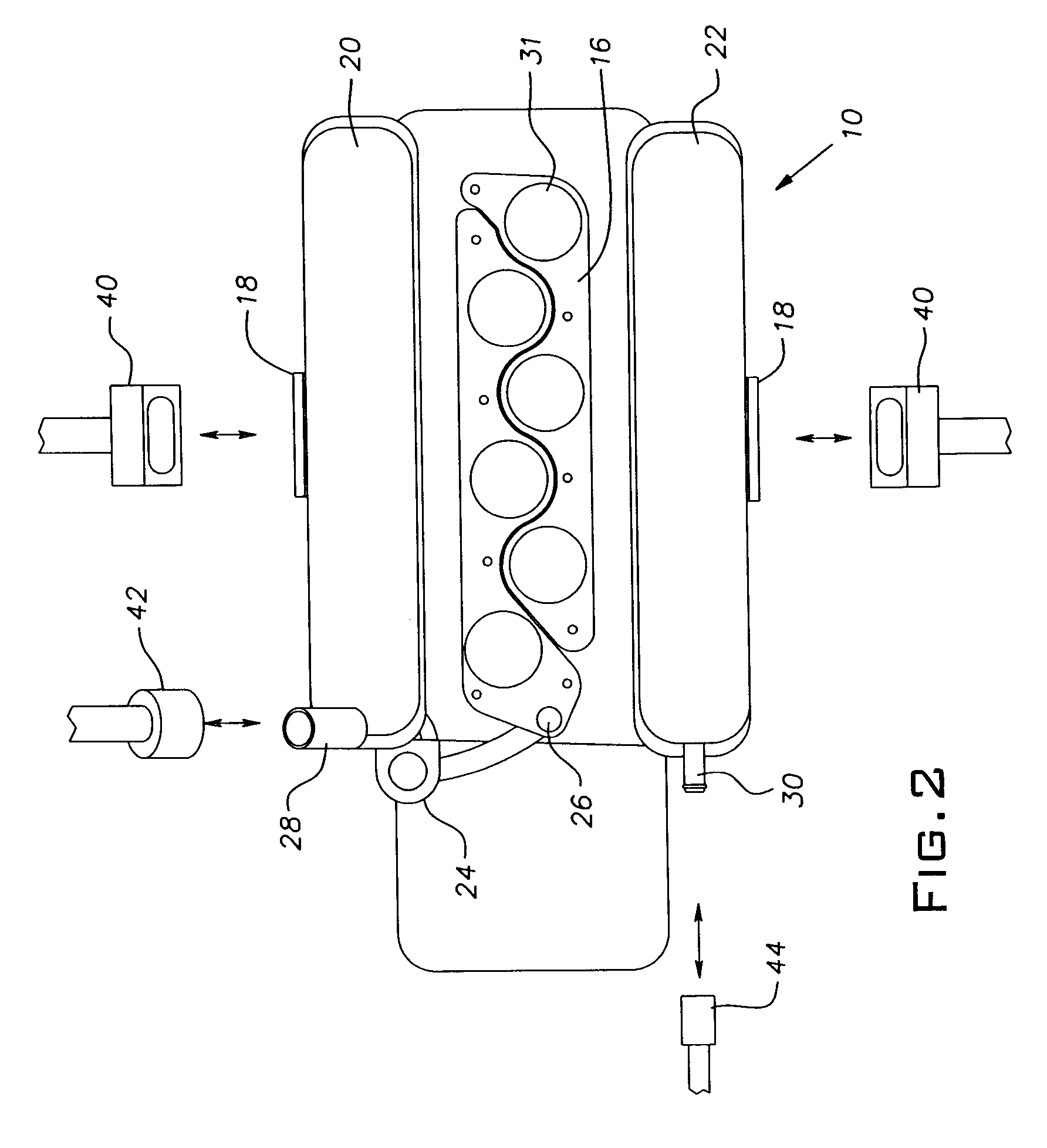
[0023]With reference to FIGS. 1-3, the engine 10 includes a cast engine block 12, a crankcase 14, an air intake base 16, a pair of exhaust manifolds 18, first and second head covers 20, 22, and an exhaust gas recirculation (EGR) valve 24.

[0024]The EGR valve 24 permits exhaust gas to be communicated from an exhaust of one or more of the engine cylinders back to an intake manifold (not shown) via the air intake base 16, so as to mix exhaust ga...

Login to view more

PUM

No PUM Login to view more

Abstract

A system and method for testing partially assembled engines for possible oil leaks. The system includes engine pressurizing devices that are automatically controlled by a controller according to a predetermined control program based upon the engine model type being tested. The pressurizing devices introduce pressurized air into the engine oil system. A leak testing unit monitors the pressurized engine for pressure drops indicative of an oil seal leak. Air pressure leaks resulting from inherently air-porous EGR valves are compensated for by an EGR compensating unit, which provides pressurized air to an intake side of the EGR valve. The flow of pressurized air through the EGR compensating unit is monitored to determine whether there is a problem with the EGR valve.

Description

CROSS-REFERENCE TO RELATED APPLICATION[0001]The present application is related to U.S. pat. application Ser. No. 11 / 325,714, filed Jan. 5, 2006, the disclosure of which is expressly incorporated herein in its entirety.BACKGROUND OF THE INVENTION[0002]1. Field of the Invention[0003]The present invention is generally directed toward manufacturing and testing methods and, more particularly, toward a system and method for testing an engine on a production line for oil leaks.[0004]2. Description of Related Art[0005]During the manufacture of an automobile engine, it is necessary to confirm that the engine's oil system does not leak. In the past, oil leak testing has been a manual operation in which an associate on the production line manually connects a flow leak tester to the engine, and the flow leak tester measures the amount of air flowing through, and out of, the oil passage. If the flow rate is greater that a predetermined limit, an alarm is sounded and the engine is sent to the rep...

Claims

Login to view more

Application Information

Patent Timeline
no application Login to view more
Patent Type & Authority Patents(United States)
IPC IPC(8): G01M15/00G01M99/00
CPCG01M3/025G01M3/3236G01M3/329
Inventor RANKIN, BRENT C.THOMAS, HEATHER W.HOKE, CHUCK
Owner HONDA MOTOR CO LTD
Who we serve
  • R&D Engineer
  • R&D Manager
  • IP Professional
Why Eureka
  • Industry Leading Data Capabilities
  • Powerful AI technology
  • Patent DNA Extraction
Social media
Try Eureka
PatSnap group products